Carrier 48DL Installation Manual
Browse online or download Installation Manual for Heat pumps Carrier 48DL. Carrier 48DL Installation manual User Manual
- Page / 84
- Table of contents
- TROUBLESHOOTING
- BOOKMARKS
- INSTALLATION 1
- TABLE OF CONTENTS 2
- LIST OF FIGURES 3
- LIST OF TABLES 3
- LIST OF TABLES (CONT’D) 4
- SAFETY CONSIDERATIONS 5
- INSPECTION 5
- REFERENCE 6
- RENEWAL PARTS 6
- APPROVALS 6
- NOMENCLATURE 7
- LIMITATIONS 9
- LOCATION 10
- RIGGING AND HANDLING 11
- FIGURE 5 - UNIT 4 POINT LOAD 11
- TABLE 3: UNIT WEIGHTS 11
- TABLE 4: 4 POINT LOAD WEIGHT 11
- CLEARANCES 12
- TABLE 5: 6 POINT LOAD WEIGHT 12
- FIGURE 6 - UNIT 6 POINT LOAD 12
- See Detail 13
- CABINET SIZE 14
- DIMENSION 14
- “A” “B” “C” 14
- 50 3/4” 28 1/4 18 1/16 28 1/4 14
- 42” 27 3/4 12 1/16 27 1/2 14
- DUCTWORK 15
- DUCT COVERS 15
- O P T I O N A L C O I L 16
- G U A R D 16
- 3 " M i n i m u m 16
- THERMOSTAT WIRING 17
- POWER AND CONTROL WIRING 17
- POWER WIRING DETAIL 17
- TABLE 8: CONTROL WIRE SIZES 17
- U N I T C O N T R O L 18
- B O A R D 18
- 264975-BIM-B-1208 19
- TABLE 29: DL PHYSICAL DATA 30
- TABLE 30: DU PHYSICAL DATA 30
- O P T I O N A L 31
- S H O W N 31
- OPTIONS/ACCESSORIES 33
- FIRE OR EXPLOSION HAZARD 33
- ADJUSTMENTS AND INFORMATION 34
- BLOWER ROTATION 36
- BELT TENSION 36
- FIGURE 25 - BELT ADJUSTMENT 36
- AIR BALANCE 56
- CHECKING AIR QUANTITY 57
- SUPPLY AIR DRIVE ADJUSTMENT 59
- OPERATION 61
- SAFETY CONTROLS 62
- COMPRESSOR PROTECTION 63
- 50” CABINET 63
- START-UP (COOLING) 66
- START-UP (GAS HEAT) 67
- CHECKING GAS INPUT 68
- TABLE 69: GAS HEAT STAGES 68
- CHARGING THE UNIT 70
- TROUBLESHOOTING 74
- OPTION BYTE SETUP 75
- HEAT DELAY SETUP 75
- TABLE 81: HEAT DELAY 76
- Power to 77
- COOLING TROUBLESHOOTING GUIDE 79
- 5005 York Drive 84
- Norman, OK 73069 84
Summary of Contents
INSTALLATION MANUALCAUTION: READ ALL SAFETY GUIDES BEFORE YOU BEGIN TO INSTALL YOUR UNIT.SAVE THIS MANUAL264975-BIM-B-1208 CONTENTSGENERAL . . . . . .
264975-BIM-B-120810 Johnson Controls Unitary Products LOCATIONUse the following guidelines to select a suitable location forthese units:1. Unit is des
264975-BIM-B-1208Johnson Controls Unitary Products 116. Maintain level tolerance to 1/2” across the entire width and length of unit.RIGGING AND HANDLI
264975-BIM-B-120812 Johnson Controls Unitary Products FIGURE 7 - UNIT CENTER OF GRAVITYCLEARANCESAll units require particular clearances for proper o
264975-BIM-B-1208Johnson Controls Unitary Products 13NOTE: A one-inch clearance must be provided betweenany combustible material and the supply ductwo
264975-BIM-B-120814 Johnson Controls Unitary Products.FIGURE 9 - BOTTOM DUCT OPENINGS (FROM ABOVE)ReturnAirSupplyAir32-11/166-13/166-13/166-13/1621-3
264975-BIM-B-1208Johnson Controls Unitary Products 15DUCTWORKDuctwork should be designed and sized according to themethods in Manual D of the Air Cond
264975-BIM-B-120816 Johnson Controls Unitary ProductsNote orientation. Panel is “insulation” side up.CONDENSATE DRAINThe side condensate drain is reve
264975-BIM-B-1208Johnson Controls Unitary Products 17THERMOSTAT WIRINGThe thermostat should be located on an inside wall approxi-mately 56 inch above
264975-BIM-B-120818 Johnson Controls Unitary ProductsFIGURE 17 - TYPICAL ELECTRONIC THERMOSTAT FIELD WIRINGW 2R CR HY 1Y 2W 1GCX 1X 3X 4A 1A 2TTW 2Y
264975-BIM-B-1208Johnson Controls Unitary Products 19FIGURE 19 - FIELD WIRING DISCONNECT - COOLING UNIT WITH/WITHOUT ELECTRIC HEATTERMINAL BLOCK TB1F
264975-BIM-B-12082 Johnson Controls Unitary ProductsTABLE OF CONTENTSGENERAL . . . . . . . . . . . . . . . . . . . . . . . . . . . . . . . . . . . .
264975-BIM-B-120820 Johnson Controls Unitary ProductsTABLE 9: ELECTRICAL DATA - DL-06 (6-1/2 TON) STANDARD EFFICIENCY W/O PWRD CONV. OUTLETTABLE 10: E
264975-BIM-B-1208Johnson Controls Unitary Products 21TABLE 11: ELECTRICAL DATA - DU-06 (6-1/2 TON) HIGH EFFICIENCY W/O PWRD CONV. OUTLETTABLE 12: ELEC
264975-BIM-B-120822 Johnson Controls Unitary ProductsTABLE 13: ELECTRICAL DATA - DL-07 (7-1/2 TON) STANDARD EFFICIENCY W/O PWRD CONV. OUTLETTABLE 14:
264975-BIM-B-1208Johnson Controls Unitary Products 23TABLE 15: ELECTRICAL DATA - DU-07 (7-1/2 TON) HIGH EFFICIENCY W/O PWRD CONV. OUTLETTABLE 16: ELEC
264975-BIM-B-120824 Johnson Controls Unitary ProductsTABLE 17: ELECTRICAL DATA - DL-08 (8-1/2 TON) STANDARD EFFICIENCY W/O PWRD CONV. OUTLETTABLE 18:
264975-BIM-B-1208Johnson Controls Unitary Products 25TABLE 19: ELECTRICAL DATA - DU-08 (8-1/2 TON) HIGH EFFICIENCY W/O PWRD CONV. OUTLETTABLE 20: ELEC
264975-BIM-B-120826 Johnson Controls Unitary ProductsTABLE 21: ELECTRICAL DATA - DL-10 (10 TON) STANDARD EFFICIENCY W/O PWRD CONV. OUTLETTABLE 22: ELE
264975-BIM-B-1208Johnson Controls Unitary Products 27TABLE 23: ELECTRICAL DATA - DU-10 (10 TON) HIGH EFFICIENCY W/O PWRD CONV. OUTLETTABLE 24: ELECTRI
264975-BIM-B-120828 Johnson Controls Unitary ProductsTABLE 25: ELECTRICAL DATA - DL-12 (12-1/2 TON) STANDARD EFFICIENCY W/O PWRD CONV. OUTLETTABLE 26:
264975-BIM-B-1208Johnson Controls Unitary Products 29TABLE 27: ELECTRICAL DATA - DU-12 (12-1/2 TON) HIGH EFFICIENCY W/O PWRD CONV. OUTLETTABLE 28: ELE
264975-BIM-B-1208Johnson Controls Unitary Products 3LIST OF FIGURESFig. # Pg. #1 UNIT SHIPPING BRACKET . . . . . . . . . . . . . . . . . . . . . 82 CO
264975-BIM-B-120830 Johnson Controls Unitary ProductsTABLE 29: DL PHYSICAL DATAComponentModels-06 -07 -08 -10 -12EvaporatorBlowerBlower, Centrifugal (
264975-BIM-B-1208Johnson Controls Unitary Products 31OPTIONAL ELECTRIC HEATThe factory-installed heaters are wired for single point powersupply. Power
264975-BIM-B-120832 Johnson Controls Unitary ProductsNOTE: Maximum capacity of pipe in cubic feet of gas perhour based upon a pressure drop of 0.3 inc
264975-BIM-B-1208Johnson Controls Unitary Products 33LP UNITS, TANKS AND PIPINGAll gas heat units are shipped from the factory equipped fornatural gas
264975-BIM-B-120834 Johnson Controls Unitary ProductsRAIN HOODAll of the hood components, including the filters, the gasket-ing and the hardware for a
264975-BIM-B-1208Johnson Controls Unitary Products 35FIGURE 23 - ENTHALPY SET POINT CHART40(4)70(21)50(10)55(13)60(16)65(18)35(2)45(7)75(24)80(27)35(
264975-BIM-B-120836 Johnson Controls Unitary ProductsPHASINGDL/DU units are properly phased at the factory. Check forproper compressor rotation. If th
264975-BIM-B-1208Johnson Controls Unitary Products 37TABLE 35: DL-06 (6-1/2 TON) STANDARD MOTOR DOWN SHOT BLOWER PERFORMANCE1 2ESP3TURNS OPEN4012345CF
264975-BIM-B-120838 Johnson Controls Unitary ProductsTABLE 37: DU-06 (6-1/2 TON) STANDARD MOTOR DOWN SHOT BLOWER PERFORMANCE1,2CFM RPMW5BHP CFM RPMW5B
264975-BIM-B-1208Johnson Controls Unitary Products 39TABLE 38: DU-06 (6-1/2 TON) OPTIONAL MOTOR DOWN SHOT BLOWER PERFORMANCE1,2CFM RPMW5BHP CFM RPMW5B
264975-BIM-B-12084 Johnson Controls Unitary ProductsLIST OF TABLES (CONT’D)Tbl. # Pg. #30 DU PHYSICAL DATA . . . . . . . . . . . . . . . . . . . . . .
264975-BIM-B-120840 Johnson Controls Unitary ProductsTABLE 39: DL, DU-07 (7-1/2 TON) STANDARD MOTOR DOWN SHOT BLOWER PERFORMANCECFM RPMW5BHP CFM RPMW5
264975-BIM-B-1208Johnson Controls Unitary Products 41TABLE 40: DL, DU-07 (7-1/2 TON) OPTIONAL MOTOR DOWNSHOT BLOWER PERFORMANCECFM RPMW5BHP CFM RPMW5B
264975-BIM-B-120842 Johnson Controls Unitary ProductsTABLE 41: DL, DU-08 (8-1/2 TON) STANDARD MOTOR DOWN SHOT BLOWER PERFORMANCECFM RPMW5BHP CFM RPMW5
264975-BIM-B-1208Johnson Controls Unitary Products 43TABLE 42: DL, DU-08 (8-1/2 TON) OPTIONAL DRIVE DOWN SHOT BLOWER PERFORMANCECFM RPMW5BHP CFM RPMW5
264975-BIM-B-120844 Johnson Controls Unitary ProductsTABLE 43: DL, DU-10 (10 TON) STANDARD MOTOR DOWN SHOT BLOWER PERFORMANCE1 2ESP3TURNS OPEN4012345C
264975-BIM-B-1208Johnson Controls Unitary Products 45TABLE 45: DL, DU-12 (12-1/2 TON) STANDARD MOTOR DOWN SHOT BLOWER PERFORMANCE1 2ESP3TURNS OPEN4012
264975-BIM-B-120846 Johnson Controls Unitary ProductsTABLE 47: DL-06 (6-1/2 TON) STANDARD MOTOR SIDE SHOT BLOWER PERFORMANCE1 2ESP3TURNS OPEN401 2 345
264975-BIM-B-1208Johnson Controls Unitary Products 47TABLE 49: DU-06 (6-1/2 TON) STANDARD MOTOR SIDE SHOT BLOWER PERFORMANCECFM RPMW5BHP CFM RPMW5BHP
264975-BIM-B-120848 Johnson Controls Unitary ProductsTABLE 50: DU-06 (6-1/2 TON) OPTIONAL MOTOR SIDE SHOT BLOWER PERFORMANCE&)0 530:%+3 &)0 5
264975-BIM-B-1208Johnson Controls Unitary Products 49TABLE 51: DL, DU-07 (7-1/2 TON) STANDARD MOTOR SIDE SHOT BLOWER PERFORMANCECFM RPMW5BHP CFM RPMW5
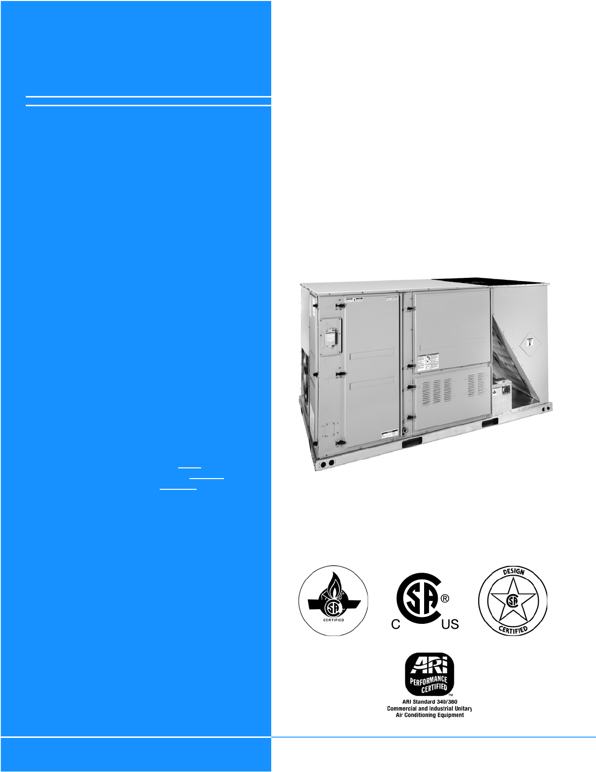
264975-BIM-B-1208Johnson Controls Unitary Products 5GENERALDL/DU units are single package air conditioners with optionalgas heating designed for outdo
264975-BIM-B-120850 Johnson Controls Unitary ProductsTABLE 52: DL, DU-07 (7-1/2 TON) OPTIONAL SIDE SHOT BLOWER PERFORMANCECFM RPMW5BHP CFM RPMW5BHP CF
264975-BIM-B-1208Johnson Controls Unitary Products 51TABLE 53: DL, DU-08 (8-1/2 TON) STANDARD MOTOR SIDE SHOT BLOWER PERFORMANCECFM RPMW5BHP CFM RPMW5
264975-BIM-B-120852 Johnson Controls Unitary ProductsTABLE 54: DL, DU-08 (8-1/2 TON) OPTIONAL DRIVE SIDE SHOT BLOWER PERFORMANCECFM RPMW5BHP CFM RPMW5
264975-BIM-B-1208Johnson Controls Unitary Products 53TABLE 55: DL, DU-10 (10 TON) STANDARD MOTOR SIDE SHOT BLOWER PERFORMANCE1 2ESP3TURNS OPEN4012345C
264975-BIM-B-120854 Johnson Controls Unitary ProductsTABLE 57: DL, DU-12 (12-1/2 TON) STANDARD MOTOR SIDE SHOT BLOWER PERFORMANCE1 2ESP3TURNS OPEN4012
264975-BIM-B-1208Johnson Controls Unitary Products 55NOTES FOR TABLE 35 THROUGH TABLE 58: • Blower performance includes dry coil and two-inchfilters.•
264975-BIM-B-120856 Johnson Controls Unitary ProductsAIR BALANCEStart the supply air blower motor. Adjust the resistances in both the supply and the r
264975-BIM-B-1208Johnson Controls Unitary Products 57CHECKING AIR QUANTITYMETHOD ONE1. Remove the dot plugs from the duct panel (for location of the d
264975-BIM-B-120858 Johnson Controls Unitary ProductsFIGURE 26 - DRY COIL DELTA P 50" CABINETDL/DU 50" CabinetIndoor Coil Pressure Drop vs.
264975-BIM-B-1208Johnson Controls Unitary Products 59SUPPLY AIR DRIVE ADJUSTMENTAt unit start-up, the measured CFM may be higher or lowerthan the requ
264975-BIM-B-12086 Johnson Controls Unitary ProductsREFERENCEAdditional information is available in the following referenceforms:• Technical Guide - D
264975-BIM-B-120860 Johnson Controls Unitary ProductsTABLE 61: ADDITIONAL STATIC RESISTANCE DL-06, -10, -12 AND DU-10, -12CFMCooling Only1Economizer2
264975-BIM-B-1208Johnson Controls Unitary Products 61OPERATIONSEQUENCE OF OPERATIONS OVERVIEWFor the DL/DU series of units, the thermostat makes a cir
264975-BIM-B-120862 Johnson Controls Unitary Productscompleted. Upon the final compressor de-energizing, theblower is stopped following the elapse of
264975-BIM-B-1208Johnson Controls Unitary Products 63condenser motor failure, (opens at 405 ± 10 psig or 440 ± 10 psig depending on unit model).3. A l
264975-BIM-B-120864 Johnson Controls Unitary ProductsFLASH CODESThe UCB will initiate a flash code associated with errorswithin the system. Refer to U
264975-BIM-B-1208Johnson Controls Unitary Products 65TEMPERATURE LIMITIf the UCB senses zero volts from the high temperature limit,the indoor blower m
264975-BIM-B-120866 Johnson Controls Unitary ProductsThe ICB monitors the Pressure and Rollout switches of gasheat units.The control circuit includes
264975-BIM-B-1208Johnson Controls Unitary Products 67POST START CHECK LIST1. Verify proper system pressures for both circuits.2. Measure the temperatu
264975-BIM-B-120868 Johnson Controls Unitary Productsvalve) clockwise to increase manifold pressure or counterclockwise to decrease manifold pressure.
264975-BIM-B-1208Johnson Controls Unitary Products 69EXAMPLE:By actual measurement, it takes 19 seconds for the hand ona 1 cubic foot dial to make a r
264975-BIM-B-1208Johnson Controls Unitary Products 7NOMENCLATURED U -10 N18 A T A AA 3 0 1 2 4 AD = A/C, Single Pkg., R-22Product CategoryA = Std. Mot
264975-BIM-B-120870 Johnson Controls Unitary ProductsCHARGING THE UNITThese units should be charged using the superheat method.Super heat charging dat
264975-BIM-B-1208Johnson Controls Unitary Products 71TABLE 73: DL-08 (8.5 TON) STANDARD EFFICIENCY SUPERHEAT CHARGINGOutdoorTemp (°F)Superheat at Comp
264975-BIM-B-120872 Johnson Controls Unitary ProductsTABLE 75: DL-12 (12.5 TON) STANDARD EFFICIENCY SUPERHEAT CHARGINGOutdoorTemp (°F)Superheat at Com
264975-BIM-B-1208Johnson Controls Unitary Products 73DU-10 (10 ton) high efficiency unit uses TXV. Charge the unit to 10° subcooling.TABLE 77: DU-07 (
264975-BIM-B-120874 Johnson Controls Unitary ProductsTROUBLESHOOTING DL/DU FLASH CODESVarious flash codes are utilized by the unit control board (UCB)
264975-BIM-B-1208Johnson Controls Unitary Products 75FIGURE 30 - UNIT CONTROL BOARDUNIT CONTROL BOARD OPTION SETUPOPTION BYTE SETUP• Enter the Option
264975-BIM-B-120876 Johnson Controls Unitary ProductsTABLE 81: HEAT DELAYHeatFan OnDelayHeat Fan OffDelayRedLED 8RedLED 4RedLED 2RedLED 160 180 On On
264975-BIM-B-1208Johnson Controls Unitary Products 77FIGURE 31 - BASIC TROUBLESHOOTING FLOWCHARTMonitorMonitoredSystemsProblem?Call forCooling?Call
264975-BIM-B-120878 Johnson Controls Unitary Products FIGURE 33 - TRIP FAILURE FLOW CHARTT r i p / F a i l u r eL o s s o fL S I n p u tE n e r g
264975-BIM-B-1208Johnson Controls Unitary Products 79COOLING TROUBLESHOOTING GUIDEOn calls for cooling, if the compressors are operating but thesupply
264975-BIM-B-12088 Johnson Controls Unitary ProductsINSTALLATIONINSTALLATION SAFETY INFORMATIONRead these instructions before continuing this applianc
264975-BIM-B-120880 Johnson Controls Unitary Productslocked out the compressor for repeat trips. The UCB should be flashing an alarm code. If not, pre
264975-BIM-B-1208Johnson Controls Unitary Products 818. If 24 volts is present at the UCB Y2 terminal, the com-pressor may be out due to an open high-
264975-BIM-B-120882 Johnson Controls Unitary Products11. If 24 volts is present at the UCB Y1 terminal and the compressor is not out due to a protecti
264975-BIM-B-1208Johnson Controls Unitary Products 839. If the blower motor runs with the fan switch in the “ON” position but does not run shortly aft
Subject to change without notice. Printed in U.S.A. 264975-BIM-B-1208Copyright © 2009 by Johnson Controls, Inc. All rights reserved. Supersedes: 26497
264975-BIM-B-1208Johnson Controls Unitary Products 9 LIMITATIONSThese units must be installed in accordance with the follow-ing:In U.S.A.:1. National
Related products and manuals for Heat pumps Carrier 48DL
 (104 pages)
(48 pages)
(28 pages)
(104 pages)
(48 pages)
(28 pages)


 (116 pages) (10 pages)
(43 pages)
(18 pages)
(120 pages)
(116 pages) (10 pages)
(43 pages)
(18 pages)
(120 pages)
© 2020, manymanuals.com. All rights reserved. | 0.165 s |
 Manymanuals.com
 Manymanuals.de
 Manymanuals.fr
 Manymanuals.it
 Manymanuals.pl
 Manymanuals.cz
 Manymanuals.es
 Manymanuals-pt.com
Comments to this Manuals