Carrier PRO-DIALOG Plus 30GK Series Specifications Page 1
Browse online or download Specifications for Household fans Carrier PRO-DIALOG Plus 30GK Series. Carrier PRO-DIALOG Plus 30GK Series Specifications User Manual
- Page / 36
- Table of contents
- BOOKMARKS
- 30GX and 30HXC series 1
- PRO-DIALOG Control 1
- Screw-Compressor Air- and 1
- Water-Cooled Liquid Chillers 1
- Table of contents 2
- BOARD DIP SWITCH (0 = open) 6
- * referred to earth 6
- PRO-DIALOG 11
- - Not in use 14
- MODE # MODE NAME DESCRIPTION 15
- ITEM FORMAT DESCRIPTION 15
- MAXUMUM RESET VALUE 20
- ZERO RESET VOLTAGE 20
- MAXIMUM RESET VOLTAGE 20
- VOLTAGE RESET REFERENVE VALUE 20
- MAXIMUM RESET VALUE 21
- T FOR ZERO RESET 21
- T FOR MAXIMUM RESET 21
- T RESET REFERENCE VALUE 21
- SUMMARY INTERFACE 27
- 0-10 V DC DEMAND LIMIT 29
- NO DEMAND LIMIT 29
- TOTAL DEMAND LIMIT 29
Summary of Contents
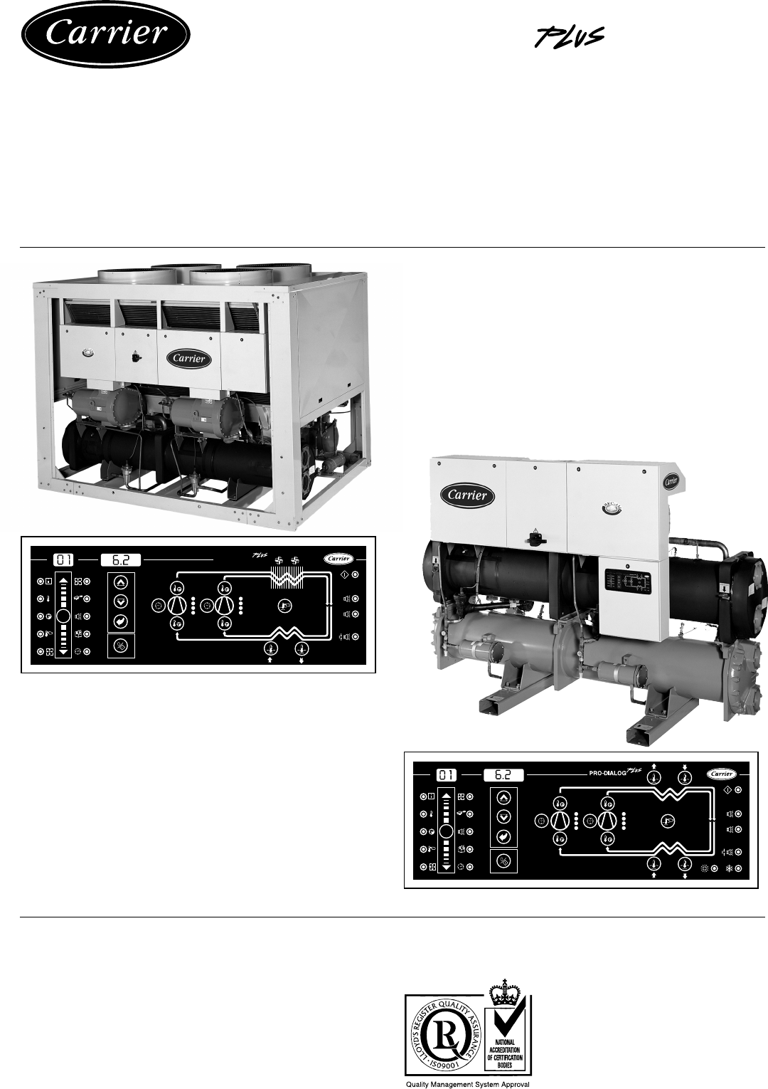
30GX and 30HXC seriesPRO-DIALOG ControlScrew-Compressor Air- andWater-Cooled Liquid Chillers50 HzInstallation, operation and maintenance in
10Earthed 24 V a.c.3.4.14 - Connection to the CCNAn RS485 bus is used for connection to the CCN. The CCNconnector is located inside the control box on
11Main interfaceBlock 1 Block 2Block 3Block 4AkPakPaBAPRO-DIALOGMENUkPaBkPakPa4 - SETTING UP PRO-DIALOG PLUS CONTROL4.1 - GeneralThe local interface
12OPERATING TYPEBlock 2 Display DescriptionLOFF Local Off: the unit is halted in local mode.L-C1 Local operation - Local On - Cooling Setpoint 1: the
135.65.95.85.7123004.2.3.3 - Modifying the value of a parameterPress the button to change to modification mode. Thislets you correct the value of a
14ITEM INFORMATION TEMPERATURES PRESSURES SETPOINTS INPUTS OUTPUTS CONFIGURATIONS ALARMS ALARMS HIST. OPERATING LOG0 Operating Evaporator Circuit A Co
15MODE # MODE NAME DESCRIPTION1 Local Off The unit has stopped in local mode because operating typeLocal Off (LOFF) has been selected with the operati
16OPERATION PRESS BLOCK 3 BLOCK 1 BLOCK 2BUTTON LED DISPLAY DISPLAYHold down the MENU buttonuntil the LED for INFORMA-TION lights.Press one of the arr
174.2.5 - Description of the TEMPERATURES menuThis menu displays the unit operating temperatures. Alltemperatures are displayed in degrees Celsius. Ac
18Item 4 Reclaim setpointThis item is used to display and modifythe reclaim setpoint. As in item 3, it isused to control condensation.Limiting values
19The reset is calculated as follows if thevalue of the “Voltage for zero reset”exceeds the value of the “Voltage formaximum reset”:• The reset is zer
2Table of contents1 - SAFETY CONSIDERATIONS ...
20000810.08 0.088 6.60.18 6.69 0.09 0.099 5.00.19 5.09 5.012 0.012 0.01212 3.00.112 3.0Let us assume that the 0-10 V d.c signalcomes from a calibrated
21Sample T reset configuration:In this example, the cooling setpoint startsto be reset with effect from a T at theevaporator of 5.0°C (full load) up
22Item 4 Demand limit contact statusWhen closed this contact limits thedemand of the unit by reference to thevalue of the demand limit setpoint, if th
23OPERATION PRESS BLOCK 3 BLOCK 1 BLOCK 2KEY LED DISPLAY DISPLAYHold down the MENU button untilthe LED for OUTPUTS/TESTSlights.Press the button to
24Item 0 PasswordA password must be entered in order toaccess the test function or modify a userconfiguration. The password has adefault value of 11.
25Item 9 CCN bus numberDefault: 0Range: 0 to 239NOTE: No two network elements can have the same elementnumber and bus number at the same time.4.2.11
26 ITEM FORMAT DESCRIPTION0* nnn Alarms history 11* nnn Alarms history 22* nnn Alarms history 33* nnn Alarms history 44* nnn Alarms history 55* nnn Al
274.3.2 - Description of the LEDsLED INDICATION WHEN LITGreen LED: the unit is authorised to start or is already runningRed LED:• Lit = circuit A or u
285.3 - Evaporator water pump controlThe evaporator water pump is started when the unit is in therunning mode described above or in delay at start-up
29• By reference to a limiting signal from a user-controlled volt-free contact: the capacity of the unit cannot exceed thedemand limit setpoint (which
34.2.10 - Description of the CONFIGURATION menu ...
305.12 - Motor cooling valve controlThe temperature of the motor windings is controlled to asetpoint of 85°C. This is achieved by cycling of the motor
31All control commands to the master/slave assembly (start/stop,setpoint, load shedding, etc.) are handled by the unit which isconfigured as the maste
32OPERATION PRESS BLOCK 3 BLOCK 1 BLOCK 2KEY LED DISPLAY DISPLAYHold down the MENU buttonuntil the LED for Alarms lights.Block 2 displays the number o
33ALARM CODE DESCRIPTIONSAlarm Description Why was this alarm Action taken Reset type Probable causecode generated? by the control1 Evaporator enterin
34Alarm Description Why was this alarm Action taken Reset type Probable causecode generated? by the control46 Oil solenoid failure, compressor A1 Oil
35ALARM CODE DESCRIPTIONS (cont.)Alarm Description Why was this alarm Action taken Reset type Probable causecode generated? by the control82 Communica
.Order No. 13056-76, 03 1999. Supersedes order No.: 13056-76, April 1998 Manufactured by: Carrier S.A., Montluel, France.Manufacturer reserves the ri
41 - SAFETY CONSIDERATIONS1.1 - GeneralInstallation, start-up and servicing of equipment can behazardous if factors particular to the installation a
5Fan start-up moduleLED - Light Emitting DiodeLoader - Compressor capacity stepLOFF - Operating type: Local offrEM - Operating type: by remote control
61 2 3 4 5 6 7 8OPENSlave board addressesBOARD DIP SWITCH (0 = open)12345678Board 4xDO #1 EXV circuit A 0 1 0 00010Board 4xDO #2
7NOTE: The external connector of the EXV must be cleaned andcoated with silicone grease (Part No. 397 EE) to keep outcondensation and prevent corrosio
824 V a.c. supply24 V a.c. supplyCon-tactorPumpEconomizer pressure sensorsThese sensors are used to measure the intermediate pressurebetween high and
9Start/stop contactSetpoint selection contactHeat/cool contactHeat reclaim selection contactDemand limit contactEvaporator water loopcontrol contact3.
More documents for Household fans Carrier PRO-DIALOG Plus 30GK Series


Related products and manuals for Household fans Carrier PRO-DIALOG Plus 30GK Series
 (14 pages)
(136 pages)
(20 pages)
(10 pages)
(11 pages)
(116 pages)
(10 pages)
(26 pages)
(14 pages)
(136 pages)
(20 pages)
(10 pages)
(11 pages)
(116 pages)
(10 pages)
(26 pages)
© 2020, manymanuals.com. All rights reserved. | 0.076 s |
 Manymanuals.com
 Manymanuals.de
 Manymanuals.fr
 Manymanuals.it
 Manymanuals.pl
 Manymanuals.cz
 Manymanuals.es
 Manymanuals-pt.com
Comments to this Manuals