Carrier 48SX024-048 User Manual
Browse online or download User Manual for Conditioners Carrier 48SX024-048. Carrier 48SX024-048 User Manual
- Page / 31
- Table of contents
- BOOKMARKS
Summary of Contents
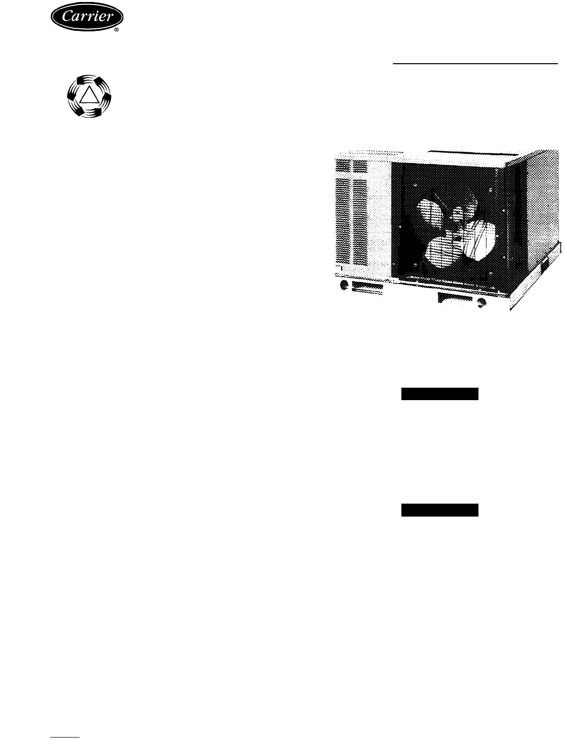
48SS018-060 48SX024-048 Packaged Gas Heating/ Electric Cooling UnitstCOMMERCIALUNITARYSYSTEMSInstallation, Start-Up and Service InstructionsCONTENTSSA
RECEIVING AND INSTALLATIONStep 1 - Check EquipmentIDENTIFY UNIT — The unit model number and serial number are stamped on unit identification pl
PART NUMBER“A”“B” PITCHFLAT50SS9000158" [203]— -50SS90001611" [279]— —50SS90001714" [356]— —PITCHED50SS900019 8" [203]10%" [2
20'1FLUSH WITH SLAB- ^ -IT___^Jr2 0”12 0”CONCRETE SU\B-Fig. 11 - Slab Mounting DetailsSECURE SCREW AGAINST BASEPAN TO HOLD LIFTING BRACKET IN PL
UNITS WITH OPTIONAL BASE RAIL - Lifting holes are provided in optional base rail as shown in Fig. 12. Operating weights are shown in Tables 1
Table 1 — Physical Data — Unit 48SSUNIT SIZE 48SS018040 024040024060 030040 030060 030080 036060036080 036100036120NOMINAL CAPACITY (ton)1V2 2 22V2 2V
Table 2 — Physical Data — Unit 48SXUNIT SIZE 48SX024040 024060030040030060030080036060036080 036100 036120NOMINAL CAPACITY (ton) 222Уг2Уг 2Уг 33 3 3OP
(Text continued from page 13)A CAUTIONUnstable operation may occur when the gas valve and manifold assembly are forced out of position w
Table 3 — Maximum Gas Flow Capacity*NOMINAL IRON PIPE, SIZE (In.)INTERNALDIAMETER(In.)LENGTH OF PIPE, FTf10 20 30 4050 60 70 8090 100125150 175200V2 .
Step 10 — Install Electrical ConnectionsFig. 20 — Vertical Discharge Cover RemovedAdhere to the following criteria when selecting, sizing,and installi
THERMOSTAT (TYPICAL)(^(y)(^(R)0LEADS (SEE UNIT WIRING LABEL)LEGEND---------Field Control-Voltage Wiring-------— Field High-Voltage WiringNOTE: Use biu
OPTIONAL RETURN AIR OPENINGREQ’D CLEARANCES FOR SERVICING In. (mm)036 (914) 36 (914) 36 (914)Duct panel Unit topSide opposite ductsCompressor access .
Table 4 — Electrical DataUNIT48SSV-PH-HZVOLTAGECOMPRESSORCONDFANINDOORPOWER SUPPLYAWG 60 CMAX WIRERANGEMOTORFANFLAMIN WIRE SIZELENGTH(ft)MinMax RLALRA
PRE-START-UPA WARNINGFailure to observe the following warnings could result in serious personal injury:1. Follow recognized safety practices a
Start Up Heating Section and Make AdjustmentsA CAUTIONComplete the required procedures given in Pre-Start-Up section above before starting the unit.A
Fig. 23 — Burner AssemblyObserve manifold pressure and proceed as follows to adjust gas input:1. Remove cover screw over regulator adjustment
MAXIMUM HIRE SIZE 2 AW6230 VOLT OPERATION AS SHOWN. FOR 208 VOLT OPERATION REVERSE RED AND ORN LEADS ON TRANSFORICR.Blower RelayContactorCapacitorCra
MAXIMUM WIRE SIZE 2 AWG^lEU)_____i~i_Sy£PU(_1 £.OtÆR__'fì_230 VOLT OPERATION AS SHOWN. FOR 208 VOLT OPERATION REVERSE RED AM) ORN LEADS ON TRANS
MAXIMUM WIRE SUPPLY_ _ft_ —YEL SIZE 2 AWS < _Blower RelayContactorCapacitorCrankcase HeaterCompressor MotorCombustion RelayEquipmentFuse LinkF
MAXIMUM WIRE SIZE 2 AWG230 VOLT OPERATION AS SHOWN FOR 208 VOLT OPERATION REVERSE RED AND ORN LEADS ON TRANSFORMERYEL—( 0FM)-6ftN-YELnBRN-VO' 1C
MAXIMUM WIRE I SIZE 2 AWG -kJBLU- EQUIP GND230 VOLT OPERATION AS SHOWN. FOR 208 VOLT OPERATION REVERSE RED AND ORN LEADS ON TRANSFORMER.COOLING FAN
MAXIMUM WIRE SIZE 2 AWG <mGRN-YEL-----111NOTES:1 If any of the original wire furnished must be replaced, it must be replaced with type 90 C wire
-45 1/2'OPTIONAL RETURN AIR OPENINGREQ’D CLEARANCES FOR SERVICING, in (mm)Duct panel Unit topSide opposite ducts Compressor access ...(Except for
Start Up Cooling Section and Make AdjustmentsA CAUTIONComplete the required procedures given in the Pre- Start-Up section on page 21 befor
Airflow can be changed by changing the lead connections of the blower motor.Unit 48SS two- or 3-speed motors (except size 030) are f
o 7/8 (22.23) ALTERNATE LV ENTRY1 1/4 (31.75)ALTERNATE POWER ENTRY1 13/16' (46.2)OPTIONAL SUPPLY AIR OPENING-4 3/4'(120 6)i12l5/1215/16(312
o 15/16^ 1 9/16' (23.8)„(39.7)¿ B.H52 49 9/16"(1320.0) (1259.3)-45 1/2OPTIONAL RETURN AIR OPENING13/16 (46 2)OPTIONAL SUPPLY AIR OPENINGC
OPTIONAL RETURN AIR OPENING1 1/4' 01.0) DIA ALTERNATE POWER ENTRY8 l/4'-< (203.6)13/16' (46 2)OPTIONAL SUPPLY AIR OPENING-4 13/16 (1
52 49 9/16"(1320.8) (1259.3)REQ'D CLEARANCES FOR SERVICING in (mm)Duct panel Unit top ... .Siete opposite ducts Compressor access (Except
RIGHT SIDE VIEWREQ'D CLEARANCES FOR SERVICING in. (mm)Duct panel ... . . 0Unit top 36(914)Side opposite ducts 36 (914)Compressor access 36(
o 15/16=^ 1 9/16' (23.8)„(39.7)^ BS2 49 g/16' (1320.8) (1259.3)OPTIONAL RETURN AIR OPENING13/16' (46 2)OPTIONAL SUPPLY AIR OPENINGRIG
Related products and manuals for Conditioners Carrier 48SX024-048
 (8 pages)
(13 pages)
(6 pages)
(26 pages)
(9 pages)
(6 pages)
(32 pages)
(16 pages)
(6 pages)
(24 pages)
(32 pages)
(0 pages)
(0 pages)
(20 pages)
(0 pages)
(20 pages)
(6 pages)
(8 pages)
(13 pages)
(6 pages)
(26 pages)
(9 pages)
(6 pages)
(32 pages)
(16 pages)
(6 pages)
(24 pages)
(32 pages)
(0 pages)
(0 pages)
(20 pages)
(0 pages)
(20 pages)
(6 pages)
© 2020, manymanuals.com. All rights reserved. | 0.065 s |
 Manymanuals.com
 Manymanuals.de
 Manymanuals.fr
 Manymanuals.it
 Manymanuals.pl
 Manymanuals.cz
 Manymanuals.es
 Manymanuals-pt.com
Comments to this Manuals