Carrier 50DP016 User Manual Page 6
- Page / 16
- Table of contents
- BOOKMARKS
- 50DP,DPE012,014 1
- 50DP016,020 1
- Single-Package Cooling Units 1
- CAUTION! 2
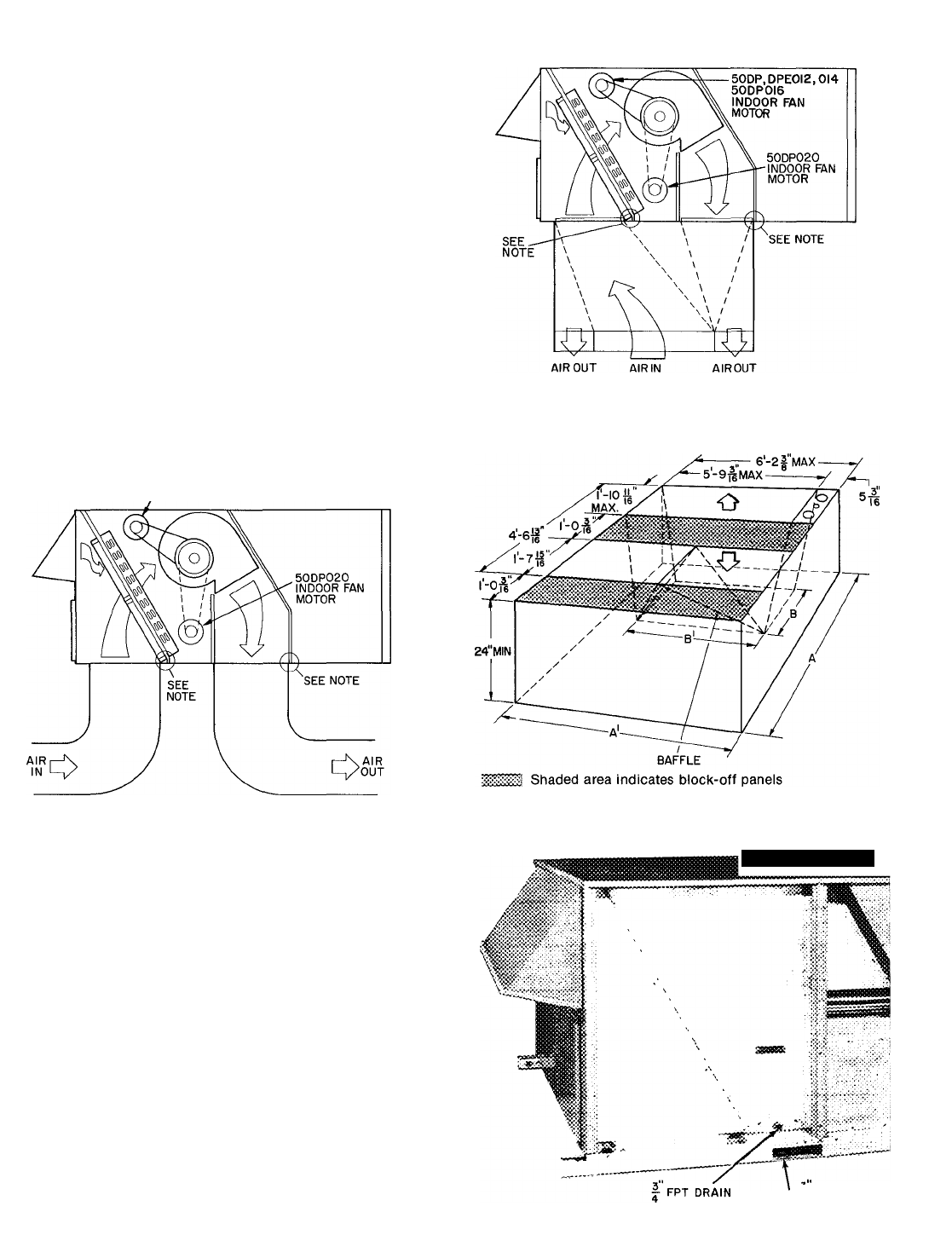
- > ALTERNATE AIRFLOW 3
- 50DR DPE0I2.0I4 50DP0I6 6
- INDOOR FAN MOTOR 6
- CONNECTION 6
- 11 DRAIN HOLES 6
- THERMOSTAT ASSEMBLY 7
- REMOVABLE JUMPER 7
- Do not manually operate 8
- / I n«/FR 10
- Table 4 — Air Quantity Limits 11
- I 2 3 4 13
- '/4 ± '/b 14
- Do not manually 15
- Tab llb 16
Related products and manuals for Conditioners Carrier 50DP016
 (33 pages)
(2 pages)
(6 pages)
(26 pages)
(16 pages)
(3 pages)
(24 pages)
(35 pages)
(0 pages)
(14 pages)
(6 pages)
(16 pages)
(12 pages)
(4 pages)
(12 pages)
(12 pages)
(12 pages)
(0 pages)
(16 pages)
(33 pages)
(2 pages)
(6 pages)
(26 pages)
(16 pages)
(3 pages)
(24 pages)
(35 pages)
(0 pages)
(14 pages)
(6 pages)
(16 pages)
(12 pages)
(4 pages)
(12 pages)
(12 pages)
(12 pages)
(0 pages)
(16 pages)
© 2020, manymanuals.com. All rights reserved. | 0.054 s |
 Manymanuals.com
 Manymanuals.de
 Manymanuals.fr
 Manymanuals.it
 Manymanuals.pl
 Manymanuals.cz
 Manymanuals.es
 Manymanuals-pt.com
Comments to this Manuals