Carrier WEATHERMAKER ZONEKIT2ZCAR Instruction Manual

Browse online or download Instruction Manual for Split-system air conditioners Carrier WEATHERMAKER ZONEKIT2ZCAR. Carrier WEATHERMAKER ZONEKIT2ZCAR Instruction manual User Manual

  • Download
  • Add to my manuals
  • Print
  • Page
    / 16
  • Table of contents
  • TROUBLESHOOTING
  • BOOKMARKS
  • Rated. / 5. Based on customer reviews
Page view 0
ZONEKIT2ZCAR
WeatherMaker® Two-Zone
Installation and Start-Up Instructions
NOTE: Read the entire instruction manual before starting the
installation.
This symbol indicates a change since the last issue.
TABLE OF CONTENTS
PAGE
Safety Considerations.....................................................................1
Installation Considerations.............................................................1
Introduction ....................................................................................1
Installation...................................................................................1-4
Sequence Of Operation...............................................................4-7
Thermostat Wiring......................................................................6-8
Care And Maintenance ..................................................................8
Troubleshooting ........................................................................9-11
Wiring Diagrams.....................................................................12-16
Wiring Diagram Notes.................................................................16
SAFETY CONSIDERATIONS
Improper installation, adjustment, alteration, service, maintenance,
or use can cause fire, electrical shock, or other conditions which
may cause personal injury or property damage. Consult a qualified
installer, service agency, or your distributor or branch for infor-
mation or assistance. The qualified installer or agency must use
factory-authorized kits or accessories when modifying this prod-
uct. Refer to the individual instructions packaged with the kits or
accessories when installing.
Follow all safety codes and wear safety glasses. Have fire
extinguisher available. Read these instructions thoroughly and
follow all warnings or cautions attached to the unit. Consult local
and state building codes and Sheet Metal and Air Conditioning
National Association (SMACNA) for special installation require-
ments.
Recognize safety information. This is the safety-alert symbol
.
When you see this symbol on the unit or in instructions and
manuals, be alert to the potential for personal injury.
Understand the signal words DANGER, WARNING, or CAU-
TION. These words are used with the safety-alert symbol. DAN-
GER identifies the most serious hazards which will result in severe
personal injury or death. WARNING signifies hazards which
could result in personal injury or death. CAUTION is used to
identify unsafe practices which would result in minor personal
injury or product and property damage.
INSTALLATION CONSIDERATIONS
1. Install in non-condensing area with ambients between 32°F
and 150°F.
2. Use vibration isolators (flex connectors) on zone dampers and
ductwork to minimize noise.
3. Place dampers away from areas that may be noise sensitive.
4. TXV is required in air conditioning and heat pump applica-
tions.
5. Use separate isolated transformer to supply power to Weath-
erMaker Two-Zone Center. (40va minimum, class 2, trans-
former, field supplied)
6. Load calculations must be performed to determine equipment
size. Equipment selection is matched to block load. It is
imperative equipment is not over sized.
7. Ductwork must be designed based off the sum of peak plus 25
percent oversize. It is imperative ductwork is not under sized.
INTRODUCTION
The WeatherMaker Two-Zone System allows the air conditioning
and heating equipment to control temperatures in 2 distinct spaces
or zones within a building. Each zone has independent temperature
settings controlled by a thermostat.
NOTE: Thermostats are purchased separately.
The comfort temperature settings can change automatically
through the use of schedules if programmable thermostats are
selected. This allows WeatherMaker Two-Zone to change the
temperature settings in zones to reflect occupancy or usage. The
WeatherMaker Two-Zone System uses motorized air volume
control dampers (also called zone dampers) to regulate the flow of
conditioned air into the zones.
INSTALLATION
Step 1—Check Equipment and Jobsite
INSPECT EQUIPMENT File claim with shipping company,
prior to installation, if shipment is damaged or incomplete.
Fig. 1—WeatherMaker Two-Zone System
(Shown Without Cover)
A97292
COMFORT ZONING SYSTEM
®
3
WARNING!
Rev
HOT parts
under this label
Y1
W1
W2
W1
W2
G
RH
RC
B
O
Y2
Y1
Equipment Term.
Sensors
HP
Duct
C1
Z
o
n
e
1
Z
o
n
e
2
Op
C
C1
Op
C
Emergency
Heat
RC-RH
Jumper
Y2
G
On
Off
24 VAC
R
W1W2 C
G
Y2
Y1
Y2
Y1
R
W1
W2
C
Equpimt
DTO
Fnc Ht
w/oF
w/F
On
Off
HP
Fnc
T'stat
Fnc
HP
Visit www.carrier.com
Manufacturer reserves the right to discontinue, or change at any time, specifications or designs without notice and without incurring obligations.
Book 1144
Tab 3a 5a 2a 5a
PC 101 Catalog No. 809-519 Printed in U.S.A. Form ZONEKIT-10SI Pg 1 10-97 Replaces: ZONEKIT-8SI
Page view 0
1 2 3 4 5 6 ... 15 16

Summary of Contents

Page 1 - WeatherMaker® Two-Zone

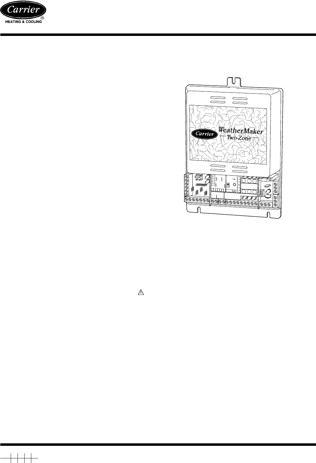
ZONEKIT2ZCARWeatherMaker® Two-ZoneInstallation and Start-Up InstructionsNOTE: Read the entire instruction manual before starting theinstallation.This

Page 2 - Fig. 4—Round Metal Ductwork

IRed LED—Displays ON when fan is energized.JRed LED—Displays ON when first-stage cooling isenergized.KRed LED—Displays ON when second-stage cooling is

Page 3

Table 3 shows a temperature/ohm/voltage relationship to help aid in troubleshooting the WeatherMaker Two-Zone System. This table willevaluate both the

Page 4

Fig. 17—Typical Fan CoilWith Single-Speed Air ConditionerA97298SINGLE-SPEEDAIR CONDITIONERTYPICALFAN COILCYGW2W3CRY/Y2OLERHGW2W1Y1Y2OBRCTWO-

Page 5

Fig. 21—Typical Fan CoilWith 2-Speed Air ConditionerA973022-SPEEDAIR CONDITIONERTYPICALFAN COILRGRCW2Y/Y2EW3LOY1CY2Y1RHGW2W1Y1Y2OBRCTWO-ZONE

Page 6 - A93494 A93495

→ Fig. 23—Single-Stage Furnace With Single-Speed Heat PumpA97615SINGLE-STAGEFURNACETWO-ZONE SYSTEMINTERFACECONTROLRGFRFWFRGTEHPOHPOTYHPCW2YORHG

Page 7

Fig. 27—Single-Stage FurnaceWith 2-Speed Heat PumpA973082-SPEEDHEAT PUMPSINGLE-STAGEFURNACERGRCWYCY2W3RHGW2W1Y1Y2OBRCTWO-ZONE SYSTEMW2Y1OSee

Page 8

Fig. 29—Typical Fan Coil With 2-Speed Heat PumpA97310RHGW2W1Y1Y2OBRC2-SPEEDHEAT PUMPTYPICALFAN COILCGW2Y/Y2RCW3LEY1RW2OW3Y1Y2OTWO-ZONE SYSTE

Page 9

Step 2—WiringTo prevent personal injury or possible equipment damage,disconnect the power supply before routing wire.All wiring must comply with local

Page 10 - Table 2—Troubleshooting

2. Properly seal joint using duct tape, mastic, or other approvedmethod. Do not allow mastic to come in contact with actuator.3. Insulate damper using

Page 11

Step 5—Install Barometric Bypass DamperNOTE: The barometric bypass damper is a critical part of theWeatherMaker Two-Zone System for control of minimum

Page 12

In automatic changeover, the zoning system works on a first comefirst serve basis. If 1 zone is calling for heating and the other forcooling, the zone

Page 13

Fig. 12—WeatherMaker Two-Zone Circuit Board with Standard Thermostat WiringA972933ThermostatZone 2Y2Y1RW1W2CGThermostatZone 1Y2Y1RW1W2CSensorsHPDuct

Page 14 - THERMOSTAT

NOTE: An HP temperature sensor must be used with a heat pumpapplication using electric strip heat. This is necessary in case theDTO is set to the Off

Page 15

timer will start counting down 15, 14, 13...0 minutes. Once thetimer expires the control will allow a new mode to restart theequipment. The internal t

Page 16

TROUBLESHOOTINGThis section contains information to assist you in troubleshootingproblems and errors associated with the WeatherMaker Two-Zonesystem.

Comments to this Manuals

No comments