Carrier start-up and Instruction Manual Page 11
- Page / 44
- Table of contents
- BOOKMARKS
- Installation, Start-Up, and 1
- Service Instructions 1
- INSTALLATION 2
- Step 1 — Check Jobsite — 2
- Step 2 — Check Unit — 2
- Step 3 — Unit Location — 3
- LEFT RETURN RIGHT RETURN 7
- Unit Hanger Detail 7
- UNIT HANGER ISOLATION DETAIL 9
- AIRFLOW CONFIGURATION 10
- Code Return Discharge 10
- L Left Top 10
- R Right Top 10
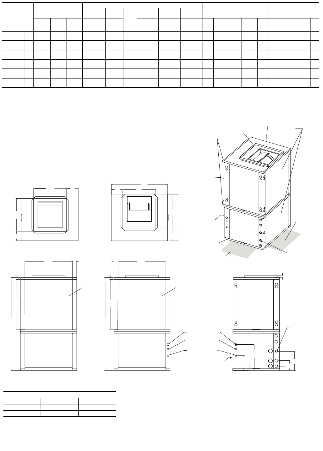
- RIGHT RETURN 11
- LEFT RETURN 11
- (right opposite) 13
- Vibration 15
- Absorption 15
- 1/4” Pitch for 16
- Drainage 16
- Pitch Toward 16
- Drain Connection 16
- Step 8 — Electrical Wiring 17
- Stg 1/Stg 2 19
- Aquazone 20
- Thermostat 20
- Step 9 — Low Voltage Wiring 28
- PRE-START-UP 28
- System Checkout — 28
- FIELD SELECTABLE INPUTS 29
- C Control DIP Switches — 29
- D Control DIP Switches — 29
- Scroll Compressor Rotation — 31
- Unit Start-Up Cooling Mode 31
- Unit Start-Up Heating Mode 31
- Flow Regulation — 32
- Flushing — 32
- SYSTEM TEST 34
- Test Mode — 34
- COAX — Coaxial Heat Exchanger 37
- Refrigerant Liquid Line Flow 37
- Book 1 4 42
- Ta b 5 a 5 a 42
- CONTROL VOLTAGE 43
- TEMPERATURES 43
- *97B0001N06* 44
Related products and manuals for Water heaters & boilers Carrier start-up and
 (22 pages)
 (8 pages)
(24 pages)
(8 pages)
(24 pages)
© 2020, manymanuals.com. All rights reserved. | 0.047 s |
 Manymanuals.com
 Manymanuals.de
 Manymanuals.fr
 Manymanuals.it
 Manymanuals.pl
 Manymanuals.cz
 Manymanuals.es
 Manymanuals-pt.com
Comments to this Manuals