Carrier 38HD User Manual
Browse online or download User Manual for Conditioners Carrier 38HD. Carrier 38HD User Manual
- Page / 12
- Table of contents
- BOOKMARKS
- Instructions 1
- [^¡©[Hlir ®DlS)i WOiW 2
- 3/4" 3
- A WARNING 6
- A CAUTION 10
- Tab 12
Summary of Contents
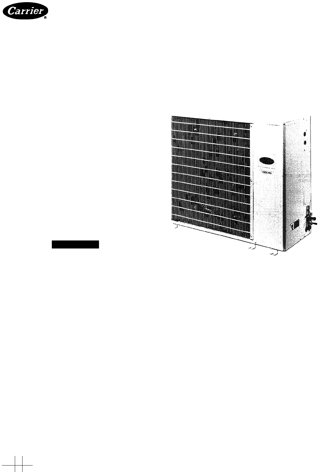
Ibl']-HEATING & COOLING38HDSplit System Condensing UnitsInstallation, Start-Up and ServiceInstructionsSAFETY CONSIDERATIONSInstalling and s
TlT23SEChOPERATINGTIME5MIN-BLK DENOTES CLOSED CONTACTSFig. 9 — Time Guard II Sequence ChartCOMPRESSORLOCKOUT<D Q <1>-BLU-(p dl-BRN BRN—(COMMO
TROUBLESHOOTING CHART — COOLING CYCLE
iManufacturer reserves the right to discontinue, or change at any time, specifications or designs without notice and without incurring obiigations.Boo
«6»CLEARANCES FOR SERVICE AND AIRFLOW, ALLOW 6 IN. ABOVE UNIT.T6 IN.HHORIZONTAL AIR DISCHARGEHIGH VOLTAGE 1-1/8' DIA.F1^ © T ¥ f:[^¡©[Hlir
f''UNITWEIGHTA B C38HD036 (108 9 kg) 240 ibs(352)1 '-1 %"(19 05) 3/4"(9 53) %"38HD048(110 7 kg) 244 ibs(347)I'-iya&
RETAINERFLARE NUTTable 1 — AccuRater Optimization ChartFLARECONNECTIONTYPE A(Arrow on AccuRater body points in metering direction.)(Arrow on AccuRat
Table 2 — Physical DataUNIT 38HD 018 024030036048060OPER WT (lb), 1 ph/3 ph148/* 160/*171/* 240/226244/235244/235REFRIGERANTR-22COMPRESSORModelOil (pt
________IARRANGEMENT A-(COOLING ONLY)ARRANGEMENT B-ONE TRANSFORMER (COOLING AND ONE-STAGE HEATING)ARRANGEMENT C-ONE TRANSFORMER (COOLING AND TWO-S
Table 3 — Electrical Data (60 Hz)OUTDOOR UNIT 38HDV/PHOPER VOLTS*COMPR FANFLAMCAMAX FUSE OR HACR TYPE CKT BKR AMPSMaxMinLRA RLA018024030036048060208/2
Charge System — Release holding charge into system by opening (backseating) liquid and suction line service valves. Add charge amou
field repaired, therefore only a complete valve or valve stem and service port caps are available for replacement.AccuRater® (Bypass Type) Ser
Related products and manuals for Conditioners Carrier 38HD
 (10 pages)
(11 pages)
(7 pages)
(6 pages)
(12 pages)
(21 pages)
(20 pages)
(12 pages)
(35 pages)
(12 pages)
(9 pages)
(6 pages)
(2 pages)
(15 pages)
(12 pages)
(12 pages)
(24 pages)
(8 pages)
(15 pages)
(8 pages)
(10 pages)
(11 pages)
(7 pages)
(6 pages)
(12 pages)
(21 pages)
(20 pages)
(12 pages)
(35 pages)
(12 pages)
(9 pages)
(6 pages)
(2 pages)
(15 pages)
(12 pages)
(12 pages)
(24 pages)
(8 pages)
(15 pages)
(8 pages)
© 2020, manymanuals.com. All rights reserved. | 0.070 s |
 Manymanuals.com
 Manymanuals.de
 Manymanuals.fr
 Manymanuals.it
 Manymanuals.pl
 Manymanuals.cz
 Manymanuals.es
 Manymanuals-pt.com
Comments to this Manuals