Carrier AQUAZONE 50RHC006-060 User Manual Page 30
- Page / 44
- Table of contents
- BOOKMARKS
- Features/Benefits 1
- Table of contents 2
- Features/Benefits (cont) 3
- Model number nomenclature 4
- ARI/ISO capacity ratings 5
- Physical data 6
- Options and accessories 7
- CARRIER AQUAZONE THERMOSTATS 8
- Dimensions 10
- VERTICAL DIMENSIONAL DATA 11
- Performance data 14
- Performance data (cont) 16
- AIRFLOW CORRECTION TABLE 25
- Electrical data 29
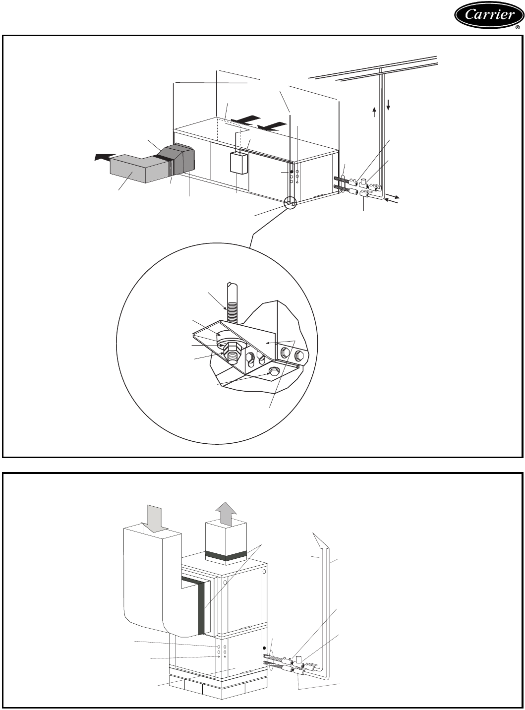
- Typical piping and wiring 30
- Typial wiring schematics 31
- Typical control wiring 33
- Application data 34
- Acoustical design 35
- WSHP sound control 35
- Horizontal units 35
- Application data (cont) 36
- Guide specifications 38
- Guide specifications (cont) 40
Related products and manuals for Heat pumps Carrier AQUAZONE 50RHC006-060
 (20 pages)
(40 pages)
(52 pages)
(31 pages)
(14 pages)
(44 pages)
(107 pages)
(24 pages)
(44 pages)
(20 pages)
(40 pages)
(52 pages)
(31 pages)
(14 pages)
(44 pages)
(107 pages)
(24 pages)
(44 pages)
© 2020, manymanuals.com. All rights reserved. | 0.055 s |
 Manymanuals.com
 Manymanuals.de
 Manymanuals.fr
 Manymanuals.it
 Manymanuals.pl
 Manymanuals.cz
 Manymanuals.es
 Manymanuals-pt.com
Comments to this Manuals