34
Aquazone™ water source heat pumps are available in a
flexible, efficient array of models, which can be used in all
types of water loop, ground water, and ground loop type
systems. Aquazone products provide optimal energy
efficient solutions and adapt to the most challenging design
requirements.
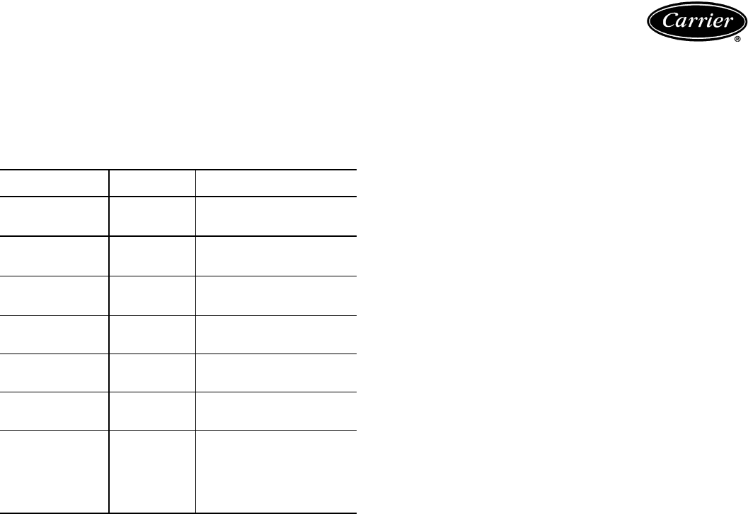
AQUAZONE PRODUCT GUIDE
Water loop system
Water loop (or boiler/tower) system applications typically
include a number of units plumbed to a common piping
system. For optimal performance, this system should be
designed between 2.25 and 3 gpm per ton of cooling ca-
pacity. The system is comprised of highly efficient pack-
aged reverse cycle heat pump units interconnected by a
water loop. The water circuit serves as both a sink and
source for heat absorption and rejection and is designed
for entering water temperatures between 60 F and 90 F.
Within this temperature range units can heat or cool as re-
quired from the same water source. Transferring heat from
warm to cold spaces in the building, whenever they coex-
ist, conserves energy rather than creating new heat.
Refer to the Carrier Water Source Heat Pump Sys-
tem Design Guide for assistance designing water loop
systems. The guide includes a practical approach for the
most current design recommendations including:
• Product application including horizontal, vertical, con-
sole, rooftop and water-to-water applications.
• Ventilation methods and system design including energy
recovery.
• Acoustical considerations for different product types.
• Addressing IAQ issues such as condensate removal,
humidity control.
• Air Distribution Design including diffuser selection/
layout and ductwork design.
• Hydronic System Design including pipe sizing/layout
and boiler/tower sizing.
• Control Configurations such as stand alone, DDC,
DCV, and VVT®.
• WSHP Efficiency/Operational Cost Comparison chart.
• System variations such as a system without a boiler,
variable pumping, and VAV for interior use.
Condensate drainage
Ven ting — Properly vent condensate lines to prevent fan
pressure from causing water to hang up in the piping.
Condensate lines should be pitched to assure full drainage
of condensate under all load conditions. Use chemical
treatment to remove algae in the condensate pans and
drains in geographical areas that are conducive to algae
growth.
Trapping — Condensate trapping is a necessity on every
water source heat pump unit. A trap is provided to prevent
the backflow of moisture from the condensate pan and into
the fan intake or downstream into the mechanical system.
The water seal or the length of the trap depends on the
positive or negative pressure on the drain pan. As a rule of
thumb, size the water seal 1 in. for every 1 in. of negative
pressure on the unit. The water seal is the distance from
the bottom of the unit condensate piping connection to
the bottom of the condensate drain line run-out piping.
Therefore, the trap size should be double the water seal
dimension.
Horizontal units — Horizontal units should be sloped to-
ward the drain at a
1
/
4
in. per foot pitch. If it is not possible
to meet the pitch requirement, a condensate pump should
be designed and installed at the unit to pump condensate
to a building drain. Horizontal units are not internally
trapped; therefore an external trap is necessary. Each unit
must be installed with its own individual trap and means to
flush or blow out the condensate drain. It is not acceptable
to use a common trap or vent for multiple units. The con-
densate piping system should not be designed with a pipe
size smaller than the drain connection pipe size.
Vertical units — Vertical units use a condensate hose in-
side the cabinet that acts as a trapping loop, making an ex-
ternal trap unnecessary. Install each unit with its own vent
and means to flush or blow out the condensate drain lines.
Do not install a common trap or vent on vertical units.
Water conditioning
In some applications, maintaining proper water quality
may require higher corrosion protection for the water-to-
refrigerant heat exchanger. Water quality varies from loca-
tion to location and is unique for each job. Water charac-
teristics such as pH value, alkalinity, hardness, and specific
conductance are important when considering any WSHP
application. Water typically includes impurities and hard-
ness that must be removed. The required treatment will de-
pend on the water quality as well as type of system. Water
problems fall into three main categories:
1. Scale formation caused by hard water reduces the
heat transfer rate and increases the water pressure
drop through the heat exchanger. As water is heated,
minerals and salts are precipitated from a solution
and deposited on the inside surface of the pipe or
tube.
50 SERIES
TYPE
SIZE (tons)
APPLICATION
50RHC,RVC
Horizontal/Vertical
Standard
Efficiency
1
/
2
-5
Efficient, compact, low cost
alternative for retrofit or new
boiler/tower systems.
50RHR,RVR
Horizontal/Vertical
High
Efficiency
1
/
2
-5
Efficient, adaptable unit for
new boiler/tower, ground
water, or ground loop systems.
50RHS,RVS
Horizontal/Vertical
Premium
Efficiency
1
1
/
4
-6
Premium, ultra efficient unit for
new boiler/tower, ground
water, or ground loop systems
50HQ,VQ
Horizontal/Vertical
Large Capacity
6
1
/
2
-25
Designed to handle large
zoned areas for all
applications.
50KQL Console
1
/
2
-1
1
/
2
Attractive design for finished
interior, under-window
installations.
50RTG Rooftop
3-20
Economical solution for IAQ
problems and tempering
ventilation air.
50RWS Water-to-Water
3-30
Used to pre-heat or cool
air and can be used as a
stand-alone or supplemental
boiler/chiller in most hydronic
heating applications. Also
conditions process fluids,
lubricants and refrigerants.
Application data
 (20 pages)
 Manymanuals.com
 Manymanuals.de
 Manymanuals.fr
 Manymanuals.it
 Manymanuals.pl
 Manymanuals.cz
 Manymanuals.es
 Manymanuals-pt.com
Comments to this Manuals