Carrier 50HQ User Manual Page 10
- Page / 34
- Table of contents
- BOOKMARKS
- Features/Benefits 1
- Features/Benefits (cont) 2
- Table of contents 2
- Maximum control flexibility 3
- Carrier’s PremierLink™ con 3
- Model number nomenclature 4
- AHRI/ISO capacity ratings 5
- Physical data 6
- Options and accessories 7
- CARRIER AQUAZONE THERMOSTATS 9
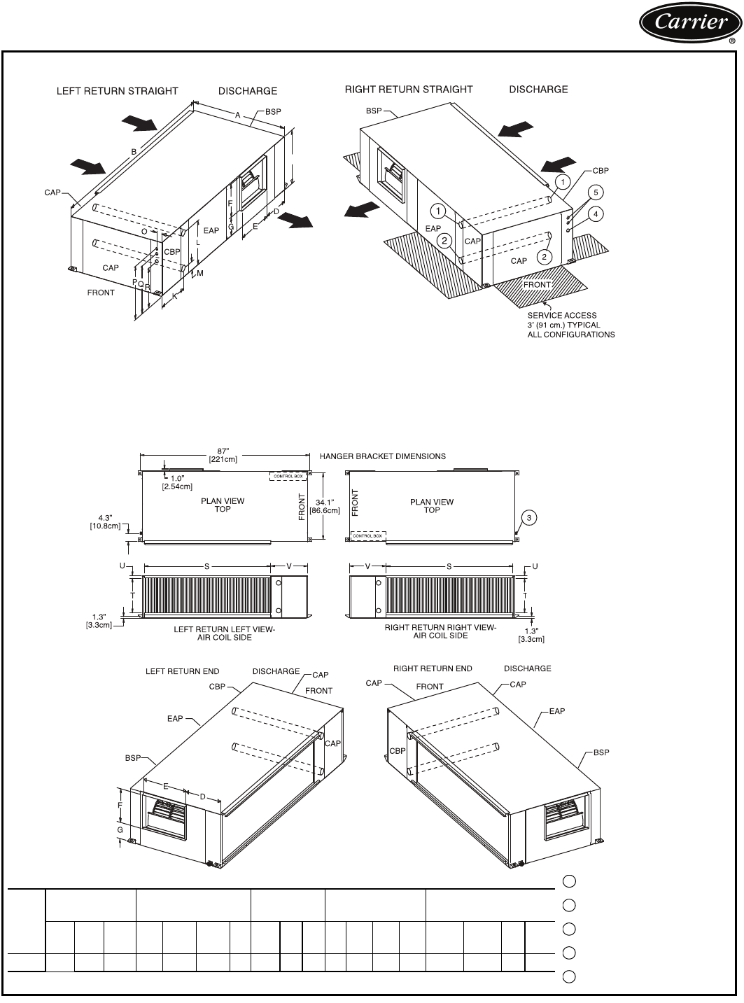
- Dimensions 10
- Selection procedure 11
- Selection procedure (cont) 12
- Performance data 13
- Performance data (cont) 14
- 50HQP096 15
- 50HQP072 BLOWER DATA 17
- 50HQP120 BLOWER DATA 19
- Electrical data 21
- Typical piping and wiring 22
- Complete C 23
- Complete C 2 23
- Complete C 1 23
- Deluxe DDeluxe D 24
- Deluxe D 2Deluxe D 2 24
- Deluxe D 1Deluxe D 1 24
- Application data 26
- Condensate drainage 27
- Water conditioning 27
- Acoustical design 27
- Application data (cont) 28
- Solenoid valves 29
- Freeze protection 29
- Guide specifications 30
- Guide specifications (cont) 32
- Replaces: New 34
- Section 6 34
- Ta b 6 a 34
Related products and manuals for Heat pumps Carrier 50HQ
 (10 pages)
(48 pages)
(14 pages)
(62 pages)
(88 pages)
(16 pages)
(52 pages)
(15 pages)
(10 pages)
(48 pages)
(14 pages)
(62 pages)
(88 pages)
(16 pages)
(52 pages)
(15 pages)
© 2020, manymanuals.com. All rights reserved. | 0.095 s |
 Manymanuals.com
 Manymanuals.de
 Manymanuals.fr
 Manymanuals.it
 Manymanuals.pl
 Manymanuals.cz
 Manymanuals.es
 Manymanuals-pt.com
Comments to this Manuals